TelephoneSystemsDirect’s core competency is selling, servicing and maintaining affordable business telephone solutions and systems that you can install yourself. We are committed to establishing and maintaining a dynamic partnership with every customer.

Business Telephone Solutions

Business Phone Service
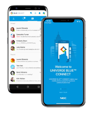
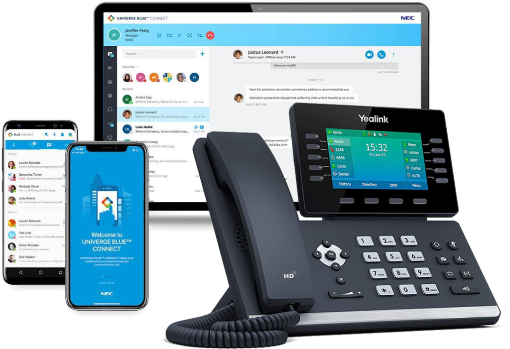
With Intermedia Unite, there is no phone system hardware to buy, install, manage, upgrade or replace. Combines your phone system, chat, video, screen sharing, file management and conference calling into a seamless business phone service that fits with your business size, needs, and work style.
Plug And Play Business Phone Systems
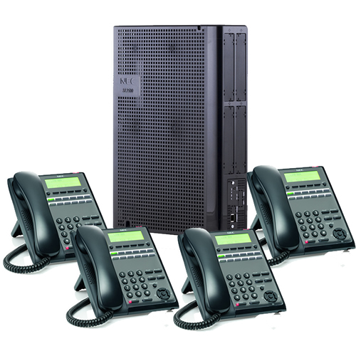
NEC SL2100 Plug and Play Telephone System With 4 Phones
Up To 3 Phone Lines
(4) 12-Button Phones
Custom Programming
Custom Day and Night Greeting
Custom Message-On-Hold
Installation Support
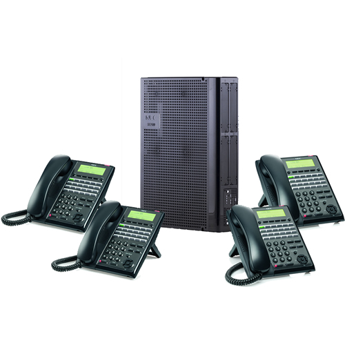
NEC SL2100 Plug and Play Telephone System With 8 Phones
Up To 6 Phone Lines
(8) 24-Button Phones
Custom Programming
Custom Day and Night Greeting
Custom Message-On-Hold
Installation Support
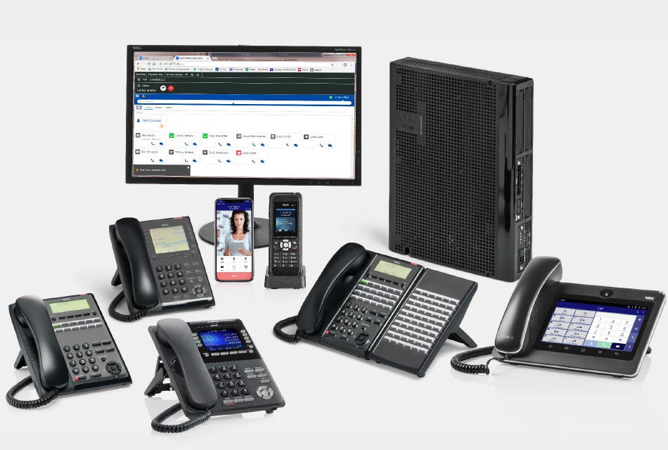
Plug And Play Telephone Systems
Plug and Play Telephone systems that are assemble, programmed and you can install yourself.
Popular Items
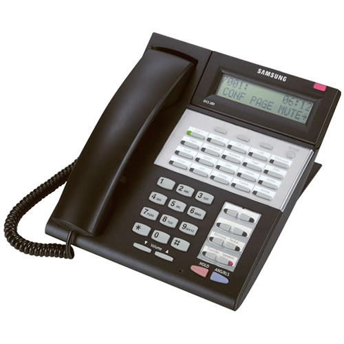
Samsung iDCS 28D 28-Button LCD Speaker Phone
Preowned Samsung iDCS 28D 28-button LCD Speaker Phone for use on the OfficeServ 7100, 7200, 7400, iDCS 500 and iDCS 100 phone systems.

Technical Support
Need help? Our technical support staff is certified on all Samsung, NEC DSX, NEC SL1100, NEC SL2100, NEC SV8100 and NEC SV9100 telephone systems. We can walk you through programming changes or troubleshooting over the phone or connect to your telephone system remotely.
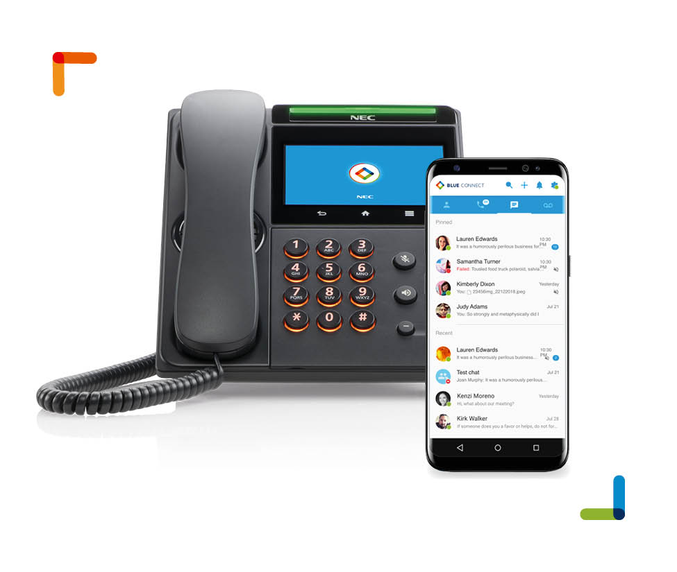
1 User NEC SL2100 Connect Bridge
With NEC SL2100 CONNECT BRIDGE you can extend your existing NEC SL2100 phone system to remote, hybrid, and mobile workers with desktop and mobile apps.
Business Phone Service For 4 Users
With our Business Phone Service For 4 Users there is no phone system hardware to buy, install, manage, upgrade or replace. Get started quickly using your current phone number and preconfigured phones to connect to the internet in no time, no complex hardware required.
Need A Custom Quote?
We’re ready to help with answers to your questions or a fast, no-obligation quote. Use the contact form below or call us at 407-818-1997, Option 1.